Designing Awards
I race on a sailboat called Scuttlebutt at Cedar Island Yacht Club. In 2025 we had a good season – first in spring, summer, fall, overall, and line honours. I wanted to make something for the crew to mark it, so I designed and made a set of custom brass awards through my manufacturing business Whatsit Manufacturing Co..
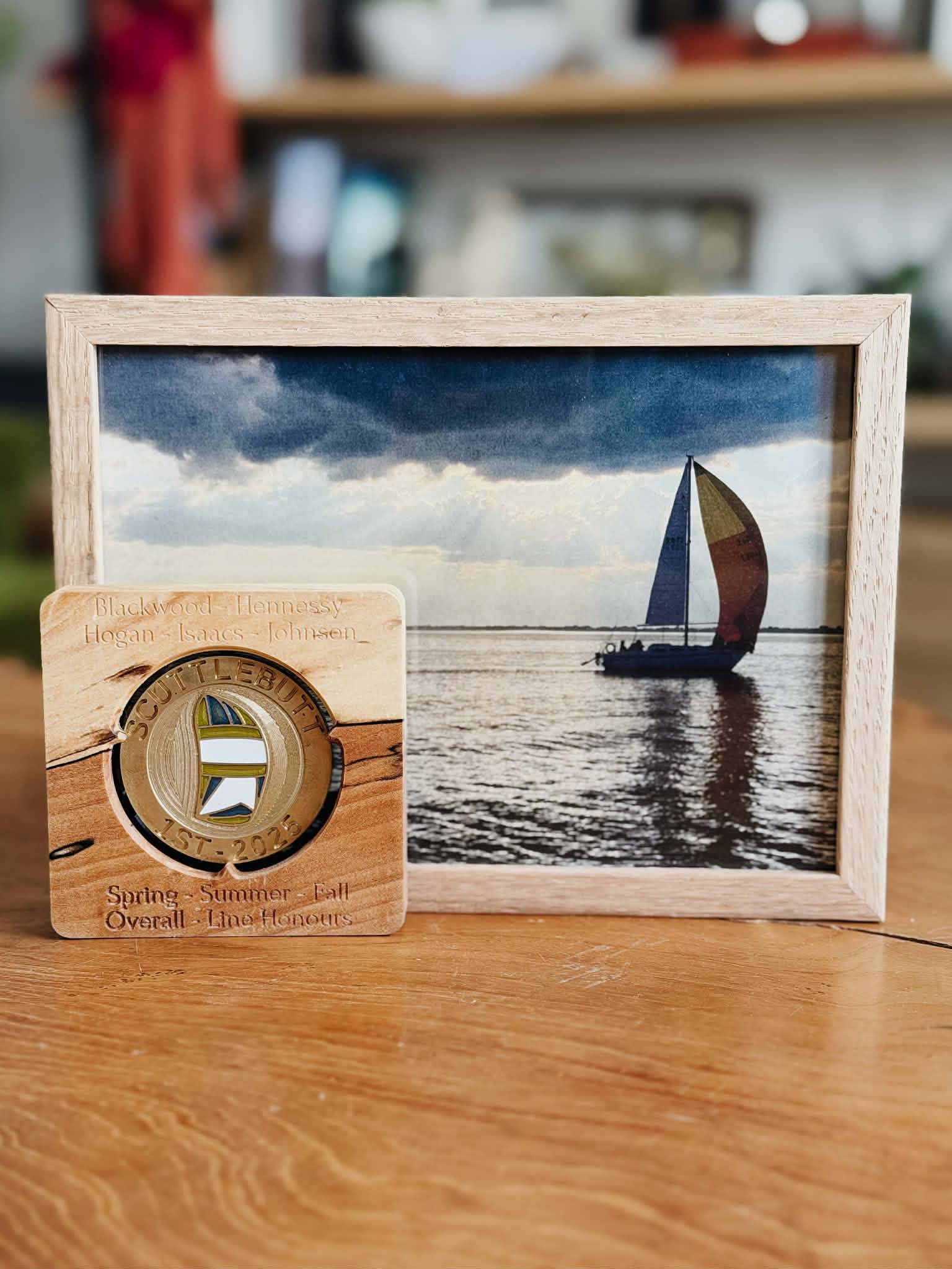
The result is a 48mm brass award with a spinnaker pattern on the front and a compass rose on the back, filled with colored epoxy to match the actual sail colors, mounted in an engraved spalted maple plate. I made eight in total – five for the crew and three that ended up as test pieces.
The design brief
I started with ChatGPT. I wanted an SVG of the award design – it said it could generate one but needed to confirm details first. Then it needed to confirm more details. Then it wrote a summary. Then it hit the usage limit. I tried again and the same thing happened. I never got more than an initial text description and one front and back image out of it, and not an image that was translatable to actual manufacture.

What ChatGPT did produce was a design specification for a 63.5mm, 6.35mm thick traditional commemorative medal – rope borders, laurel branches, a sailboat scene, matte stipple textures, crew names on the back. None of those dimensions matched my stock (100x100x4mm brass plates), and most of the features were impractical at any size I could actually cut.
The descriptions were useful for thinking about what elements mattered though, and for thinking about how to design the award: where to place details, what details, etc. I moved to OpenSCAD with Claude Code for the actual design work.
Scaling to 48mm and design challenges
Given the 100x100x4mm plate stock, a lot of the early design work was figuring out how to fit 2 or 4 awards per plate at the largest possible diameter, accounting for tool bit widths and clearances.
The first OpenSCAD commit had twisted rope borders and knurling – looked great on a computer, but not as great in a 3D printed test and completely impractical for machining with the CNC router. Switching to a flat border solved a bunch of machining challenges – a flat surface gives you something to hold and a consistent edge to clamp. Trying to add the rope border as an engraving didn't look great either, and was going to be almost as difficult to machine cleanly.
Putting text into the border did look good, so I experimented with variations: Scuttlebutt, 1st, crew names. Crew names were particularly challenging – my crew have long names and there just wasn't enough space to fit them while maintaining cuttable sizes (minimum path width of 0.6mm). Even placing the names in the center on the back was problematic due to length. Eventually the design consolidated into a compass rose on one side with compass directions in the border, and a spinnaker on the other with the boat name, year, and position in the border.
The spinnaker

Scuttlebutt's spinnaker has a distinctive pattern: blue and green panels with white sections between them, and the sail number 74090.
The first attempt at representing the sail used a depth map – a PNG heightmap generated with an online AI tool, then manually edited to clean it up. This was rendered as 3D relief in the central pocket. It worked in OpenSCAD, but flat engravings on the CNC don't follow the curved surface of a billowing sail, so I switched approaches.
The second approach traced the panel outlines from the reference photo into an SVG, then used a Python script to convert the SVG bezier curves into OpenSCAD polygon coordinates. Each panel gets a different height – 0.2mm for the outermost panel, stepping up through 0.4mm, 0.6mm, 0.8mm, and 0.9mm, to 1.0mm for the innermost panels – creating a layered topographic effect.
The raised brass lines between panels are the sail seams. The pockets between the lines get filled with colored epoxy.
The panel border generation had some issues. The standard edge-offset algorithm for creating inset pockets worked fine for the larger panels, but failed on the narrow diagonal strips. These panels are thin enough that the offset produces self-intersecting or null polygons. I switched to centroid scaling for those – scaling the polygon toward its center by a small factor (1.5-2% in/out) instead of offsetting each edge. Not as geometrically precise, but it produced valid shapes.


The sail numbers looked good on screen but were too small to read in a 3D print test. I tried a few variations but in the end removed them – it made the award easier to color and easier to machine.
The compass rose
The back has a compass rose in the central pocket with compass markings in the border. The rose is two four-pointed stars layered on top of each other, rotated 45° apart, with concentric brass rings between them. The border has engraved N/E/S/W letters at the cardinal positions, tick marks at the intercardinals, and small dots between them.
The compass originally included a third inner star but I removed it – three overlapping star geometries at this scale would have been difficult to machine cleanly, and the two-star version was already visually busy enough. Getting the borders and pockets right took trial and error and some math to make sure everything was actually machinable. Pocket depth was another variable – deep enough for the epoxy inlays, but not deeper than needed given how shallow the depth of cut had to be and how easily the bits broke.
The border markings went through similar iteration. The N/E/S/W letters were straightforward, but the tick marks and dots needed careful sizing to be both visible and cuttable.

Epoxy inlays
The epoxy inlay approach came out of the difficulty I had with the 3D relief. Instead of trying to machine a complex 3D sailboat scene, I could machine flat pockets and fill them with color.
On the front, the sail panel pockets get epoxy matching the actual spinnaker colors: blue, green, and white. The border text was going to get filled with black, but after doing the sail it looked great without it. I tested black fill on some of the failed pieces and it was fine, but less is more here.
On the back, the inner star pocket gets black epoxy, the middle star gets red, and the space between the rings gets white. The engraved compass letters and dots were going to get black fill too but didn't make it into the final awards. They don't stand out quite as well unfilled, but I think the epoxy would have distracted from the compass rose too much.
The epoxy is UV-cured. I applied each color with a 10ml syringe, using the needle to work the epoxy into tight corners. Each color (or sometimes each section) was partially cured before moving to the next, to prevent accidentally mixing or moving epoxy between adjacent colors. Once all the epoxy was applied to one side, I cured it for five minutes under UV light and then did the other side.
The mounting plate
The award sits in an engraved spalted maple plate with rounded corners. The initial plate design was a 150mm x 70mm rectangle done in OpenSCAD with Claude Code, 10mm thick – a parametric model with a stepped pocket, tabs for retention, and crew names engraved along the side. That got the basic concept right, but the final plate went through two more iterations directly in FreeCAD without Claude, shrinking to an 80mm x 80mm square, 15mm thick, with crew names above the award and the series results below.
The final version has three triangular tabs that grab the outer edge of the award, in a larger circular hole that allows the entire award to be visible. A 3D-printed plastic piece with three similar tabs slides into a pocket on the back. The gap between the wood and plastic tabs is slightly less than the award thickness, so when pushed together both deform slightly and hold the award securely. The back piece is plastic so it would be flexible enough to grip the maple and not move.
The plastic backing plate also has pockets for friction-fit magnets, so the whole thing can be placed on any magnetic surface for display in addition to sitting on a shelf or desk.
The front of the plate is engraved with crew names and the achievement labels: "Spring - Summer - Fall" and "Overall - Line Honours". The engravings did not turn out as visible as I had hoped – the spalting runs through the letters on some of the finished pieces and makes them difficult to read. If I were to make more I might add paint to the engravings or a darker finish (or might not).
Manufacturing
The entire award model is parametric OpenSCAD. The OpenSCAD output gets imported into FreeCAD for toolpath generation. Each side gets two operations: roughing with a 3.175mm endmill, then finishing with a 0.5mm tapered ball nose bit (SpeTool W01001).
For double-sided machining I designed an award holder in FreeCAD and 3D-printed it. It screws into the CNC spoilboard and clamps the edge of the award, with a small tab for alignment so the front and back sides are registered correctly.
Cutting the blanks from the 100x100mm brass plates was its own challenge. I used a 3.175mm flat endmill and held the plate to a block of wood with double-sided tape. The tape didn't stick well in every case, and the initial attempts at cutting blanks with a 0.9mm endmill did not go well – I broke four of those. After the blanks were roughed out, most had excess material from machining issues that got cut off at a bandsaw, and then each edge was brought into tolerance with a belt sander and patience. The finishing passes with 0.5mm tapered bits were equally fragile – I went through nine of them. In total, three of the eight awards ended up as unintended test pieces due to feeds and speeds issues.
Once machined, the awards were sanded up to 3000 grit before the epoxy work. I used a mirror as a flat surface with sandpaper taped to it, and a custom 3D-printed jig to hold the awards. Each grit was sanded in one direction only, rotating 90 degrees for each subsequent grit, with a thorough wash between steps. This produced a mirror finish on all the full-height areas, though it will dull over time.
The machined pockets were left mostly as-is. Small burrs were removed with a dental pick where needed, but the machining marks were kept as a decorative element.
FreeCAD and OpenSCAD
FreeCAD compatibility shaped the OpenSCAD design more than I expected. OpenSCAD's offset() function, minkowski() sums, and complex boolean intersections all caused problems on import. The plate module went from using minkowski() for rounded edges to a plain rectangle with fillets added in FreeCAD. Star pocket shapes went from offset() to manual radius calculations. By the end, the OpenSCAD code uses only basic CSG primitives – cylinders, cubes, linear extrusions of simple polygons – specifically to keep FreeCAD happy.
FreeCAD was a challenge – the award geometry ended up dense enough that FreeCAD struggled to perform well with it. I tried recreating some of the award directly in FreeCAD and even importing an SVG to work from, but both were problematic. Curved text in FreeCAD is impractical. FreeCAD also often couldn't generate toolpaths that lined up with the award geometry, or couldn't generate a path at all for certain areas, and I'd have to go back and change the design to accommodate it.
The OpenSCAD CAD work was entirely co-authored with Claude Code. Claude was effective at generating the parametric geometry, though it often took too many attempts and very direct instruction. Using git to track changes was key – reverting to the last commit and trying a different approach was a frequent pattern. The plate and fixture design happened later in FreeCAD directly, without Claude.